SSM2164 in CircuitJS
# wtf is a SSM2164
The SSM2164 is an integrated circuit, containing 4 independent VCAs (voltage controlled amplifiers), originally made by Analog Devices. It has been obsolete for a while, but due to its vast use in many analog audio circuits, various clones/replacements by different manufacturers are still getting produced to this day. Namely the AS2164 (ALFA), SSI2164 (Sound Semiconductor) and V2164 (Coolaudio, caution Behringer) are still available, cheap, and easy to find.
# wtf is a CircuitJS
CircuitJS is an open source, electronic circuit simulator, created by Paul Falstad and Iain Sharp, which runs in your browser. Its my personal favorite considering circuit simulation, because it enables one to test simple circuits and iterate on them incredibly quickly, but also still handles mildly complex ones well enough to be useable (if you have some patience). Created simulations are trivial to share (simply via a link), but can also be saved locally.
# The Issue
So whats the problem?
Simply put: CircuitJS doesn't have a builtin building block for a 2164 style VCA.
Motivation
I've lately been working on the second revision of my eurorack output module (the protorack E-201) and decided to switch the design from using 2 LM13700s (dual OTA) to a single AS2164 IC.
The new voltage controlled panning section of said module uses a sinus approximation circuit (based on a simple inverting amplifier with a diode in the feedback loop), which requires some more or less precise resistor ratios, which I'm unable to calculate, thus I'm just resorting to trial and error for finding them. This is a relatively easy process in simulation, but would be pretty tedious to do on a breadboard (unless you enjoy sitting down with an octave or two of E24 resistors, testing about what feels like possibly every single combination for about an hour), especially because I don't have access to a proper function generator (yet).
Anyways, after fiddling around with that for a while, I realized I could use the two remaining VCAs I hadn't used yet in said circuit, and thus it became crucial for me, to be able to simulate them.
So I decided to poke around for a bit.
# Bringing the 2164 to CircuitJS
First thing I tried was the "Voltage Controlled Voltage Source" (VCVS).
I dragged one in, set the Output Function to a * b, connected two signals, a test point and
BANG!
there's your VCA, end of the blogpost...
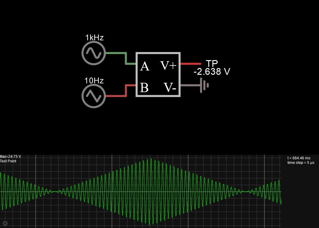
Wellllll, it's not that easy sadly. While what we got here is a basic VCA, well actually ... a pretty advanced one with perfect linear voltage control and support for negative control voltages (aka four quadrant multiplier), that's not really what we are looking for.
(Don't get me wrong, this is a super useful building block if you want to quickly sketch out a circuit or already have a building block like this in actual hardware. But I'm looking for a good approximation of the exact VCA of the 2164, because thats the chip I'm actually going to use, so the search goes on.)
So back to the drawing board? ... Not really. Let's take a look at what we are missing.
# Exponential Response
First thing is the exponential -33mV/dB response the 2164 offers.
The amplification the control input b introduces should actually be:
This is still in dB though, thus we still need to convert it to linear:
Finally we just need to multiply the resulting linear amplification with the value of the
actual signal input a, therefore:
So let's use a*10^(-b/0.033/20) as the Output Function for the VCVS.
Et voila! A nice exponential response!
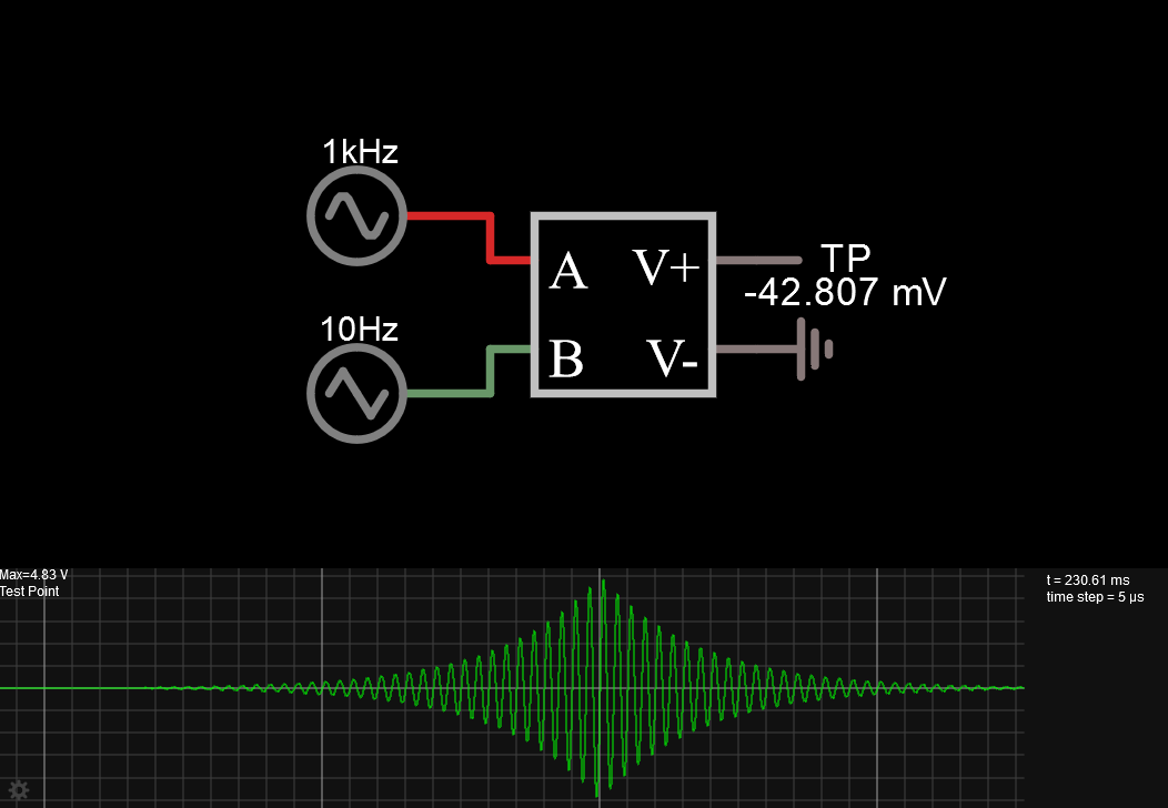
(Note that I had to take down the control signal quite a bit and also add a significant DC offset. Without those changes, the output voltage would go up to a few hundred Megavolts!)
# VCVS vs CCCS
The second problem is, that a careful look at one of the many 2164 datasheets, reveals that only its control input is voltage based, while the signal input and output work via currents.
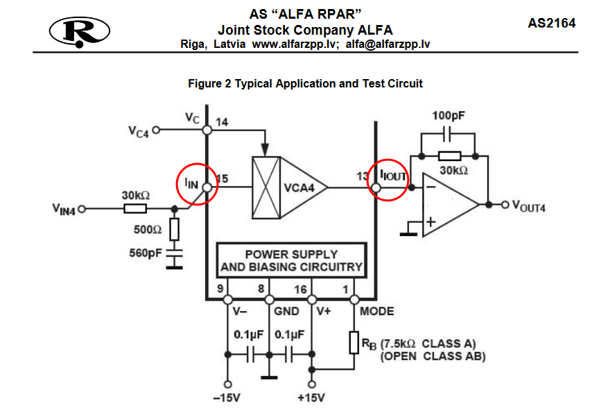
So what we'd actually need is a "Current and Voltage Controlled Current Source". The closest thing we got in CircuitJS is the "Current Controlled Current Source" (CCCS) which works just fine and also gives us the opportunity to set the input impedance of the control input appropriately.
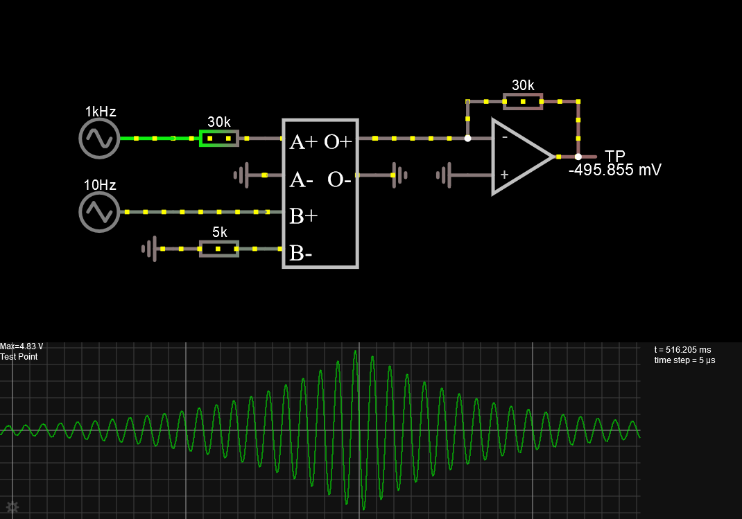
Okay, so let's add one of them in. Hm. Now we got two inputs labeled A+ and A- and the formula
only uses a as a variable.
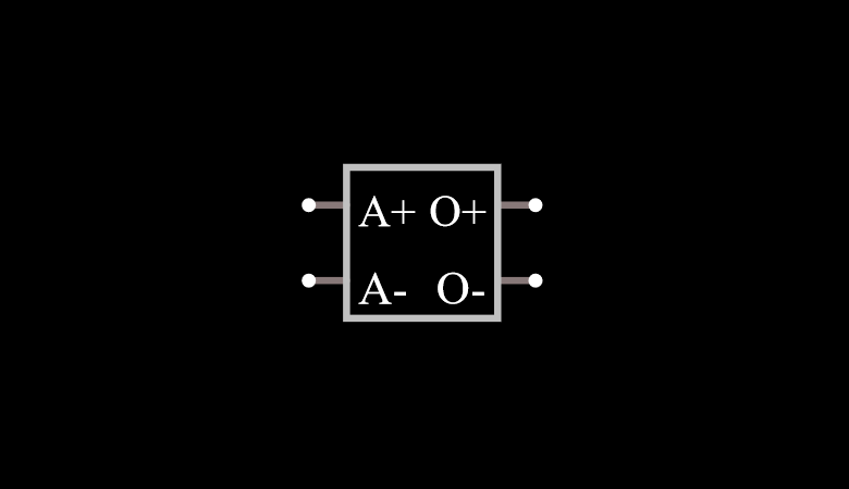
Sooooo, guess we'll add another 2 inputs then. Okay, now we got A+, A-, B+ and B-, that looks good. We can also already enter our Output Function from earlier while we are at it.
Next, let's add an input resistor between A+ and our input signal and also connect A- to ground. The way the 2164 example circuit is structured, it'd make sense for that input to be connected to a virtual ground internally, also the input current has to flow somewhere I guess.
For the output, we'll connect O+ like shown in the example circuit too. The opamp just acts as a simple current to voltage converter. We'll also connect O- to ground, because it seemingly has to be connected to something and O+ is already connected to a virtual ground anyways.
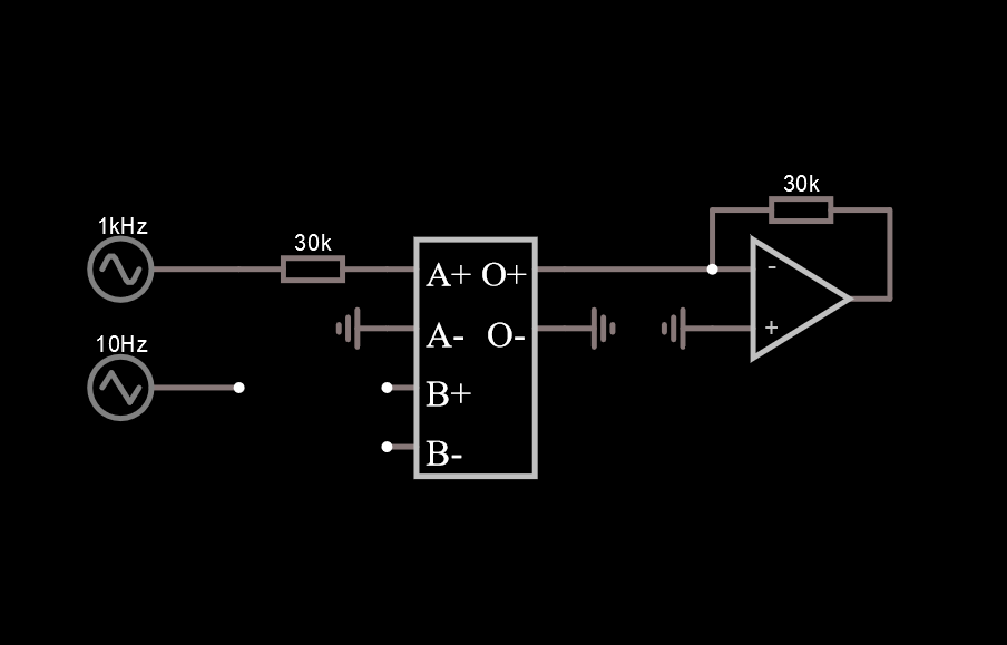
So what about B? Guess we'll do the same thing, connect B- to ground and just connect the modulation signal aaaaand ... oh.
Well that isn't working, we're getting a "Singular Matrix!" error in the bottom left corner which freezes our simulation immediately.
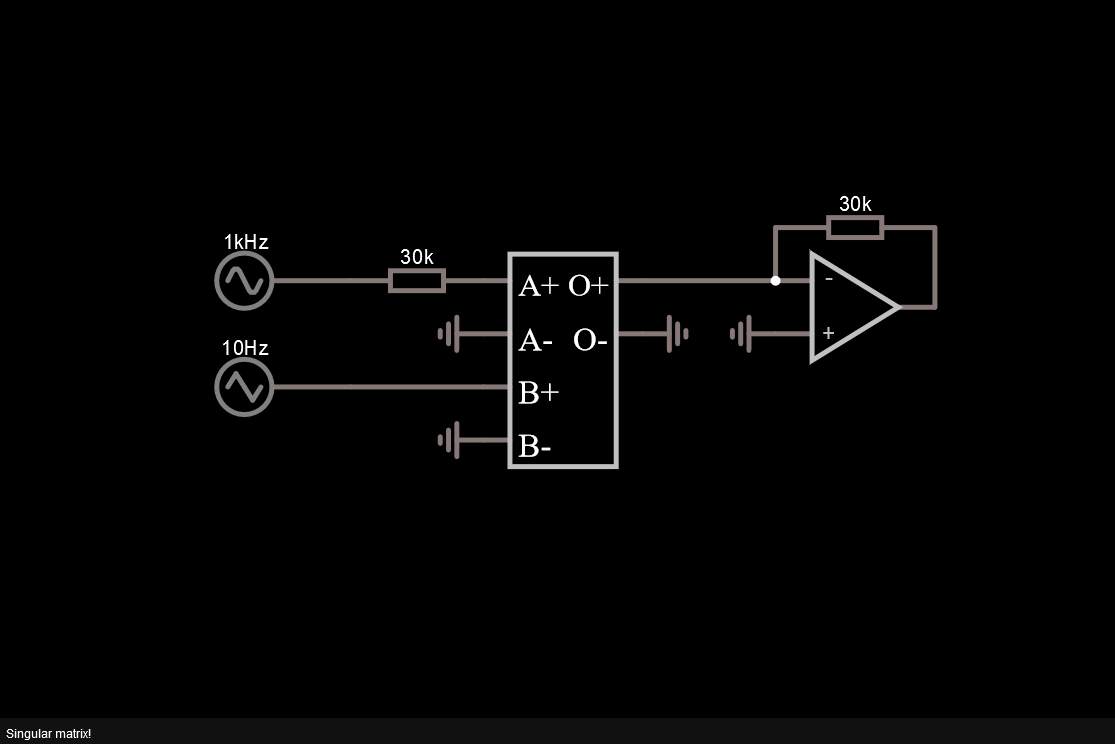
Let's think about this again! If the CCCS only measures the current between the input terminals (B+ and B-), we basically shorted our modulation signal to ground. That can't be good.
So let's add another resistor inbetween. The actual 2164 chip doesn't need any resistor though, so we'll add it between B- and ground, as an "internal" resistor, kind of. A 1k should do for now.
Bingo! Well ... atleast kind of!
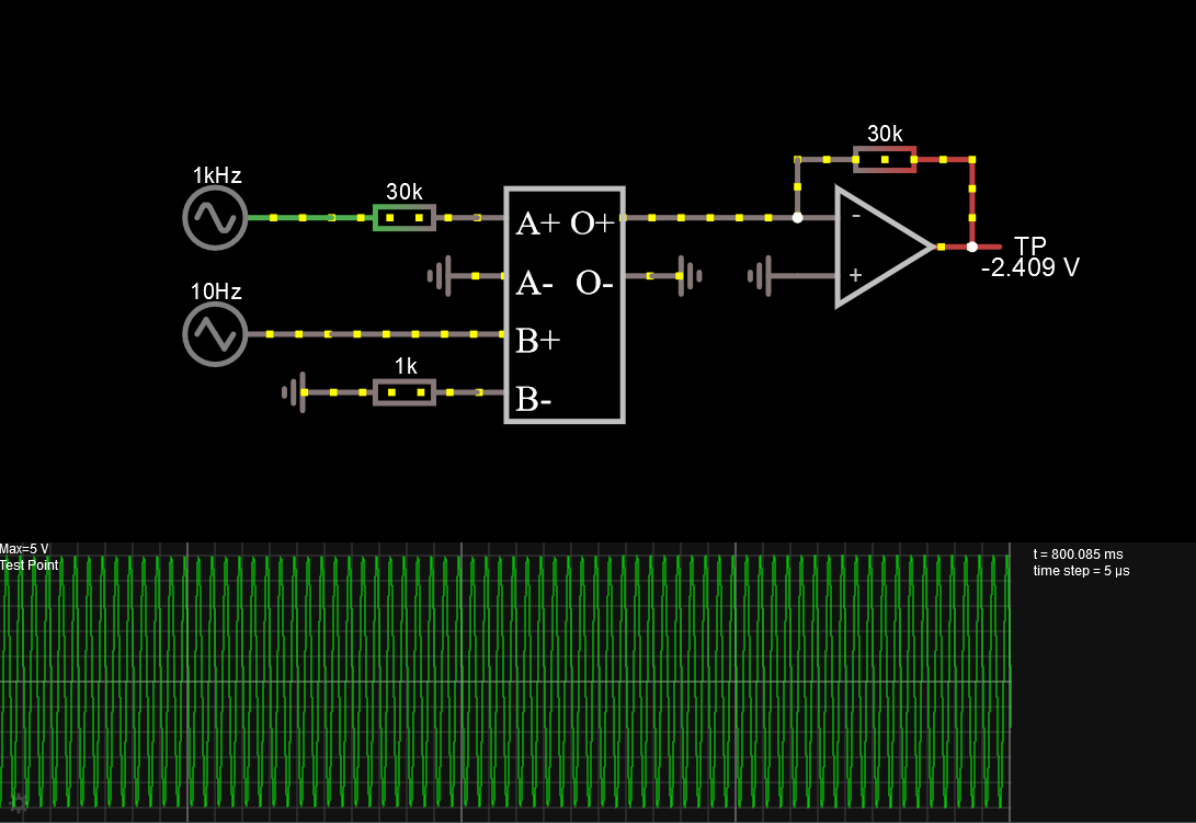
So it's working again, but the modulation signal doesn't seem to have any effect on the input signal.
Although ... if you look carefully at the "Max" value of the scope, you might be able to see it dropping from 5V down to 4.991V every now and then. Maybe it's just the wrong resistor value!
Let's drop it to 100, 10 ... 1! There we go! (no more screenshots, hit the link and change it yourself ...)
So it's working now, but we also got like 1.5A flowing through that resistor. Not great, not terrible.
But actually, if you think about it, this makes a lot of sense. The CCCS measures the current between B+ and B-, but what we really want, is the voltage at B+. By dropping the resistor to a 1Ohm one, we basically set the numerical ratio between the measured current and the actual voltage we want to measure to 1 (aka they are equal).
So let's do something more reasonable, looking at the datasheet again, the input impedance of
the control input is supposed to be 5kOhm. So let's set the resitor to that and instead
multiply b by 5000 in our Output Function, to get the ratio to 1 again:
a*10^(-b*5000/0.033/20).
Well would you look at that! We get the same result and with that, a working emulation of the 2164 VCA section!
# Conclusion
After using the described Output Function for a while, I added one last thing.
A min statement, which limits the gain of the VCA to +20dB (which is the max gain,
according to the datasheet).
Without this tweak, the exponential function would frequently overflow, crashing my
simulations. Thus, I'd recommend using this as the final equation:
a*10^(min(20,-b*5000/0.033)/20).
Apart from that, it seems to work flawlessly.
# TLDR
If you want to use 2164 like VCAs in CircuitJS:
- add a Current Controlled Current Source
- edit it to use
4inputs anda*10^(min(20,-b*5000/0.033)/20)as the Output Function - connect A- and O- to ground
- connect B- to a 5k resistor to ground
- A+ will act as Iin, O+ as Iout and B+ as VC
